Why Your Concrete Keeps Cracking: 5 Rebar Detailing Mistakes Hiding in Plain Sight
Walk into any construction site where concrete cracks have appeared, and you'll hear the same frustrated conversation. The project manager blames the concrete mix. The contractor points to weather conditions. The quality inspector mentions curing protocols.
But here's what TAS has helped clients prevent over 13 years:costly failures that start in the rebar layout drawings.
Concrete and steel are partners in every reinforced structure. Concrete handles compression brilliantly - bearing enormous downward weight. Steel is the tension specialist, absorbing the pulling, bending, and stretching forces that would otherwise tear concrete apart. When this partnership works, structures stand for generations. When it fails, cracks appear within months.
The issue isn't usually the amount of steel specified - those calculations are typically spot-on. The breakdown happens in translation, when engineering intent gets lost between the drawing board and the construction site. Poor rebar detailing creates invisible weak points that concrete exposes through the only language it knows:cracking.
Let's examine five detailing oversights that repeatedly show up in real-world projects, and how to prevent them before concrete gets poured.
1. The Cover Thickness Problem: When Protection Becomes Proximity
Concrete cover is the protective layer between rebar and the structure's outer surface. It's the primary defense keeping moisture, oxygen, and corrosive chemicals away from steel reinforcement.
What Goes Wrong
During site installation, several factors push steel closer to formwork than intended. Tie wires add unexpected thickness. Stirrup dimensions get approximated. Cover blocks - the plastic or concrete spacers maintaining correct distance - are placed too far apart or skipped to save time. Heavy rebar cages sag against formwork under their own weight.
TThe tolerance for error is razor-thin. A design calling for 40mm cover that delivers 20mm has cut the protection in half.
The Consequence
When rebar rusts, the oxidized material expands to approximately six times the original steel volume. Inside hardened concrete, this expansion generates internal pressure that causes a predictable sequence: rust stains appear first, followed by surface cracks along rebar lines, then chunks of concrete spalling off completely.
In coastal environments or areas using de-icing salts, what might take 20 years in a dry climate can happen in 5 years.
The Fix
Detailing drawings must specify clear cover requirements for each element type - 40mm for exposed columns, 50mm for foundations, 20mm for protected interior slabs.
On site, use the right number of appropriately sized cover blocks, rigidly tied at intervals that prevent sagging. A simple visual inspection before formwork closes can prevent years of expensive repairs.
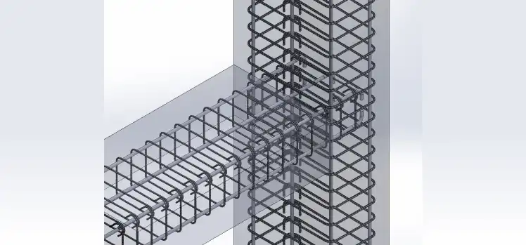
2. Beam-Column Joints: Where Anchorage Failures Begin
Beam-column connections are stress concentration zones, especially under lateral forces from wind or seismic activity. Tension forces from beam reinforcement must transfer smoothly into the supporting column through proper anchorage.
What Goes Wrong
To simplify shop drawings or speed up installation, beam top bars sometimes get terminated with straight cuts at the column face. When hooks are provided, they occasionally lack the required development length—the minimum bar length needed for concrete to grip the steel and prevent pullout.
The Consequence
Under load, inadequately anchored bars can physically slip inside the concrete. The joint opens with wide diagonal cracks radiating from the connection point. During seismic events, these joints can fail catastrophically, allowing beams to separate from columns.
The Fix
Beam top reinforcement must be anchored into columns using 90-degree hooks. The total embedded length - from the column face through the hook's tail - must satisfy the calculated development length (Ld).
At TAS, we use detailing software with 3D modeling capabilities (Revit, Tekla Structures, STAAD Pro) that includes rebar validation tools flagging inadequate anchorage before drawings reach fabrication.
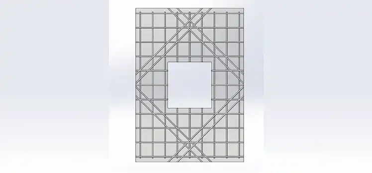
3. Openings in Slabs: The Forgotten Corner Reinforcement
Whenever a slab includes an opening - for staircases, elevator shafts, HVAC ducts, or skylights - sharp internal corners create stress concentration points that standard slab reinforcement cannot handle.
What Goes Wrong
Many detailing drawings show the regular mesh pattern but omit special reinforcement needed around openings. The assumption is that existing mesh will accommodate the opening. It won't.
The Consequence
As concrete shrinks during curing or deflects under load, stress focuses intensely at 90-degree internal corners. Without adequate reinforcement, diagonal cracks inevitably radiate outward from corners, often appearing within weeks of concrete placement.
The Fix
Proper detailing requires diagonal reinforcement bars at 45-degree angles across each re-entrant corner, in both top and bottom of the slab. These "corner trimmers" or "hairpin bars" intercept diagonal tension forces before they crack the concrete.
Additionally, frame the opening perimeter with straight bars that replace the steel area removed by cutting the hole—similar to how a window frame strengthens a wall opening.
BIM-based projects show that automated clash detection identifies missing corner reinforcement during 3D modeling, preventing these oversights.
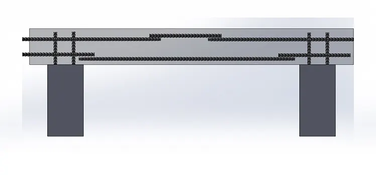
4. Splice Locations: Putting Weak Points Where Strength Is Needed Most
Steel reinforcement bars come in standard lengths (typically 12 meters). For longer members, bars must be spliced—overlapped so forces transfer from one bar to the next through surrounding concrete.
What Goes Wrong
Site convenience often dictates splice locations. Fixers overlap bottom bars at mid-span because that's where bar lengths naturally meet. Top bars get spliced directly over columns for the same reason. Both locations are exactly wrong.
The Consequence
A beam experiences maximum positive bending at mid-span, creating maximum tension in bottom reinforcement. Placing lap splices there creates a weak point precisely where the structure needs maximum strength, resulting in vertical flexural cracks propagating upward.
Similarly, maximum negative moment (and top reinforcement tension) occurs over supports. Splicing top bars there has the same weakening effect.
The Fix
Bottom bars should be spliced near supports where bending moments are minimal. Top bars should be spliced in the middle third of the span where top bar tension is lowest.
When multiple bars must be spliced, stagger them so they don't all occur at the same cross-section. If four bottom bars need splicing, offset them by a meter or more along the beam.
Recent fabrication software introduced optimization algorithms that reduce splice requirements by ordering bars in project-specific custom lengths. Some 2025 projects reported reducing splices by 40%, with corresponding improvements in structural performance.
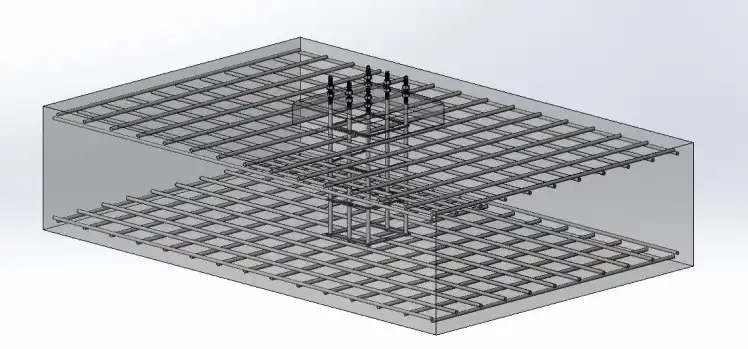
5. Temperature and Shrinkage Steel: The Invisible Stitching
Concrete isn't static after placement. It shrinks as it dries over months and expands/contracts daily with temperature fluctuations. In large concrete surfaces, these volume changes generate internal tensile stresses.
What Goes Wrong
For one-way slabs carrying loads in a single direction, detailers sometimes provide structural reinforcement only in the load-bearing direction, assuming the perpendicular direction doesn't need steel.
The Consequence
Without steel to restrain shrinkage, concrete cracks to relieve internal tension. The pattern is distinctive: random "map cracking" (spider-web appearance) or wide, regularly spaced shrinkage cracks perpendicular to main reinforcement. This allows moisture penetration, reduces service life, and creates aesthetic problems.
The Fix
Building codes specify minimum reinforcement ratios for temperature and shrinkage control—typically around 0.18% of the concrete cross-sectional area. This "distribution steel" runs perpendicular to main structural reinforcement.
Think of it as stitching. The steel doesn't prevent shrinkage, but it holds the concrete together, keeping shrinkage cracks microscopically tight (less than 0.3mm) rather than allowing a few wide cracks to develop.
Revit 2026 introduced enhanced temperature steel templates that automatically calculate and place distribution reinforcement based on slab dimensions, eliminating the risk of omission.
The Real-World Cost of Detailing Errors
Rebar detailing mistakes hit project budgets hard:
- Caught during detailing: 2-4 hours to revise drawings
- Caught during fabrication: Material waste + 1-2 week delays
- Caught after concrete placement: - 50-100x more expensive to fix Prevention is always cheaper than remediation.
How Modern Technology Is Reducing Errors
The shift from 2D CAD to 3D BIM modeling has transformed detailing quality. Tools like Tekla Structures, Revit, and STAAD Pro provide:
Automated clash detection – Identifies conflicts before fabrication (reduces on-site rework by 65-75%)
Code compliance checks – Verifies development lengths, cover distances, and spacing automatically
3D visualization – Makes missing elements and congestion issues immediately visible
Material optimization – Reduces rebar waste by up to 25% through intelligent layout planning
At TAS Engineering, we integrate these BIM capabilities throughout every structural project, delivering clash-free, constructable rebar detailing that arrives on site ready for installation.
The Bottom Line: Concrete Tells the Truth
Cracks appear exactly where detailing failed to handle tension:
- Insufficient cover → rust expansion cracks
- Poor anchorage → diagonal joint cracks
- Missing corner steel → cracks radiating from openings
- Wrong splice locations → mid-span flexural cracks
- No distribution steel → map cracking and shrinkage splits
Every failure is preventable through disciplined detailing, 3D modeling, systematic quality checks, and clear communication between stakeholders.
At TAS Engineering, 13 years of experience across 120+ projects has taught us one truth: the best concrete repairs are the ones you never need to make.
Need Precision Structural Engineering?
TAS Engineering delivers execution-ready structural detailing including rebar modeling, BIM coordination, and clash-free shop drawings for manufacturing, infrastructure, and commercial construction projects.

Ideas Are Easy. Execution Is Engineering.
Our team helps turn complex concepts into buildable solutions.